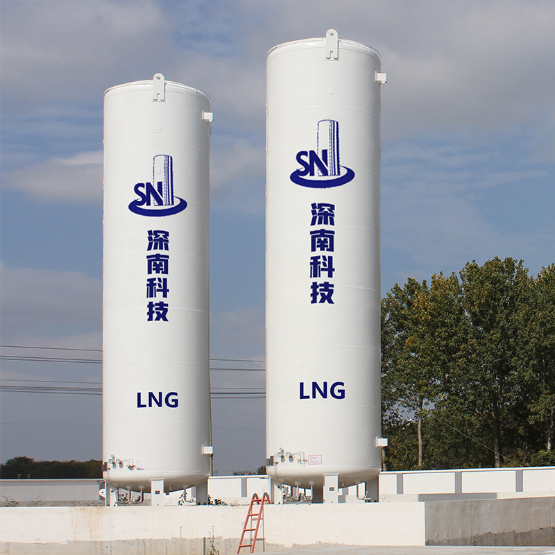
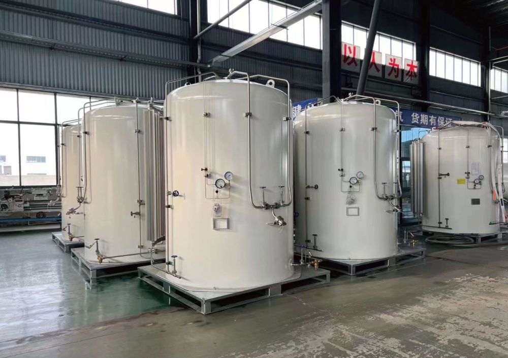
Vertical Cold Stretch Storage Systems
Product Advantages
The inner liner adopts helium mass spectrometry leak detection to ensure airtightness;
The quality assurance system is complete. Perfect manufacturing process;
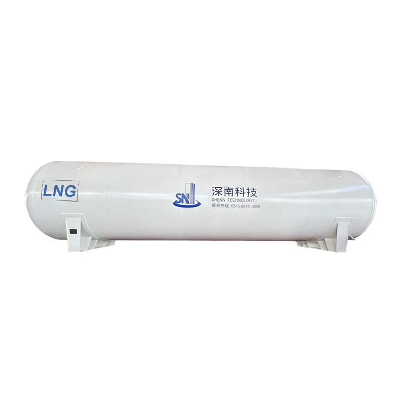
Technical parameters of vertical LNG storage tank (LNG storage tank)
| Serial Number | Specification and model | Overall dimensions | weight(kg) | notes |
| 1 | CFL-5/0.8 | Φ1916×5040 | 3800 | support |
| 2 | CFL-10/0.8 | Φ2316x5788 | 5500 | support |
| 3 | CFL-15/0.8 | Φ2316x 7725 | 7500 | support |
| 4 | CFL-20/0.8 | Φ2416×8902 | 8700 | support |
| 5 | CFL-30/0.82 | Φ2916× 8594 | 11600 | support |
| 6 | CFL-50/0.8 | Φ3116×11392 | 17900 | support |
| 7 | CFW-50/0.8 | Φ3216×10842 | 17500 | support |
| 8 | CFL-60/0.8 | Φ3016×14365 | 21400 | support |
| 9 | CFW-60/0.8 | Φ3216×12462 | 20500 | support |
| 10 | CFL-100/0.8 | Φ3420×17666 | 34800 | support |
| 11 | CFL-150/0.8 | Φ3720×21128 | 50900 | support |
| 12 | CFL-200/0.8 | Φ4024x22855 | 62300 | skirt |
| 13 | CFL-60/1.44 | Φ3016×14551 | 24400 | support |
Features
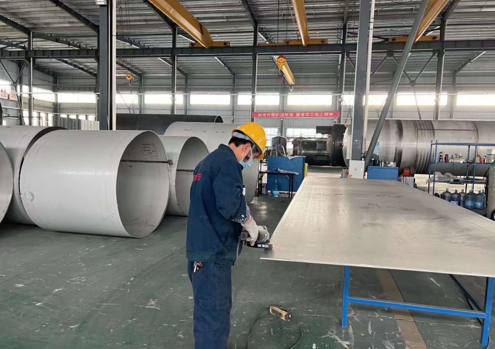
● Inner Vessel: Optimized design and manufacture of austenitic stainless steel for cryogenic liquid applications.
● Outer container: Carbon steel is equipped with unique lateral support and lifting lugs for transportation, which is convenient for safe transportation, lifting and low-cost installation.
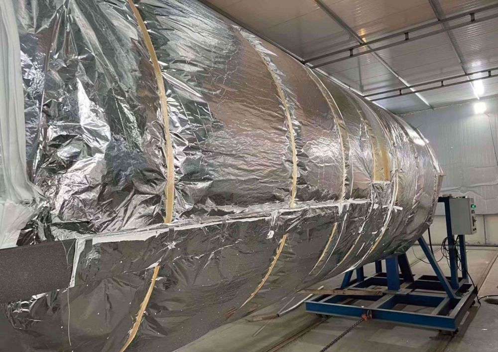
Insulation system: Unique internal structure design, advanced vacuum equipment and perfect detection means ensure excellent insulation performance and long-term vacuum performance. Commitment to three-year vacuum warranty.
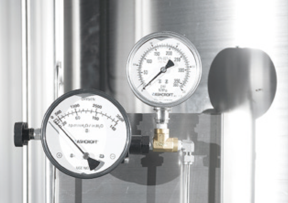
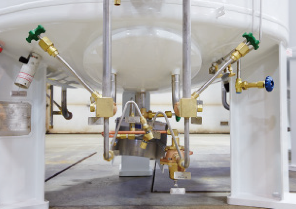
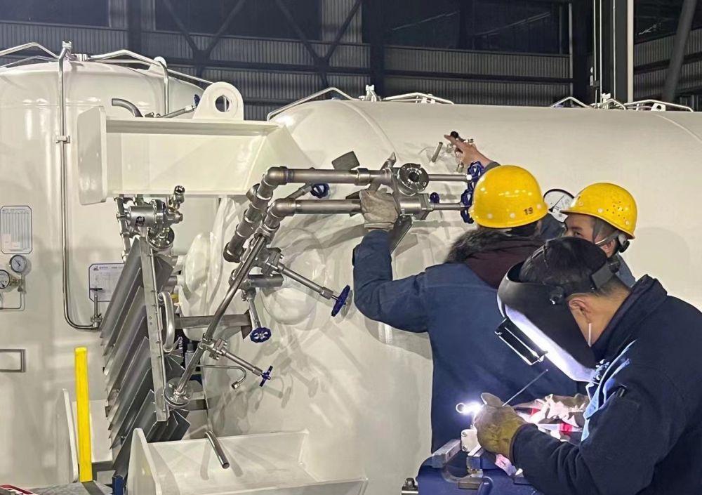
● Valve pipeline system: compact modular pipeline design, minimizing external pipeline loss; adopting combined valve mode, reducing welding joints, reducing costs, and reducing maintenance costs; adopting ergonomic principles to design pipelines The process flow, valves and instruments are in the best position for easy operation; all stainless steel pipeline system is stable and durable; the internal pipeline design uses advanced engineering software from the United States for flexible calculation and inspection to ensure product quality.
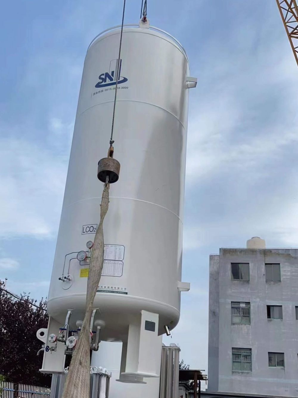
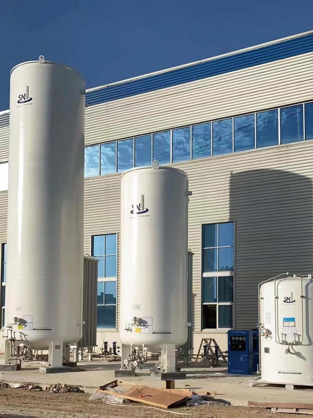
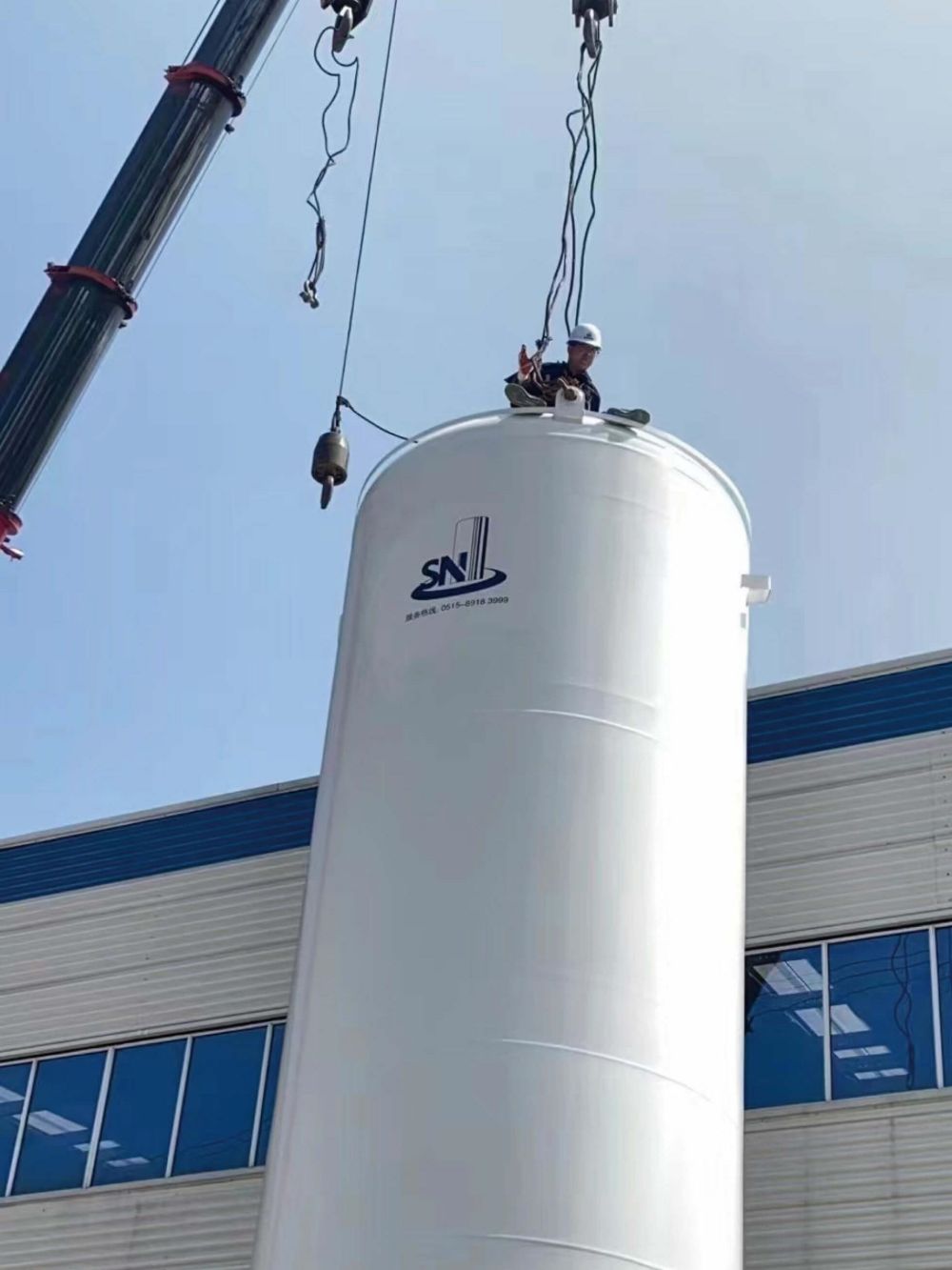
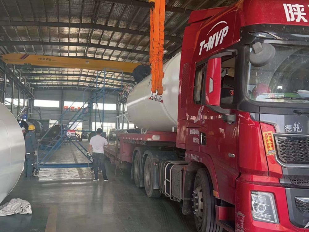
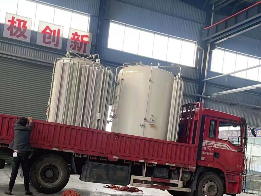
Installation Site
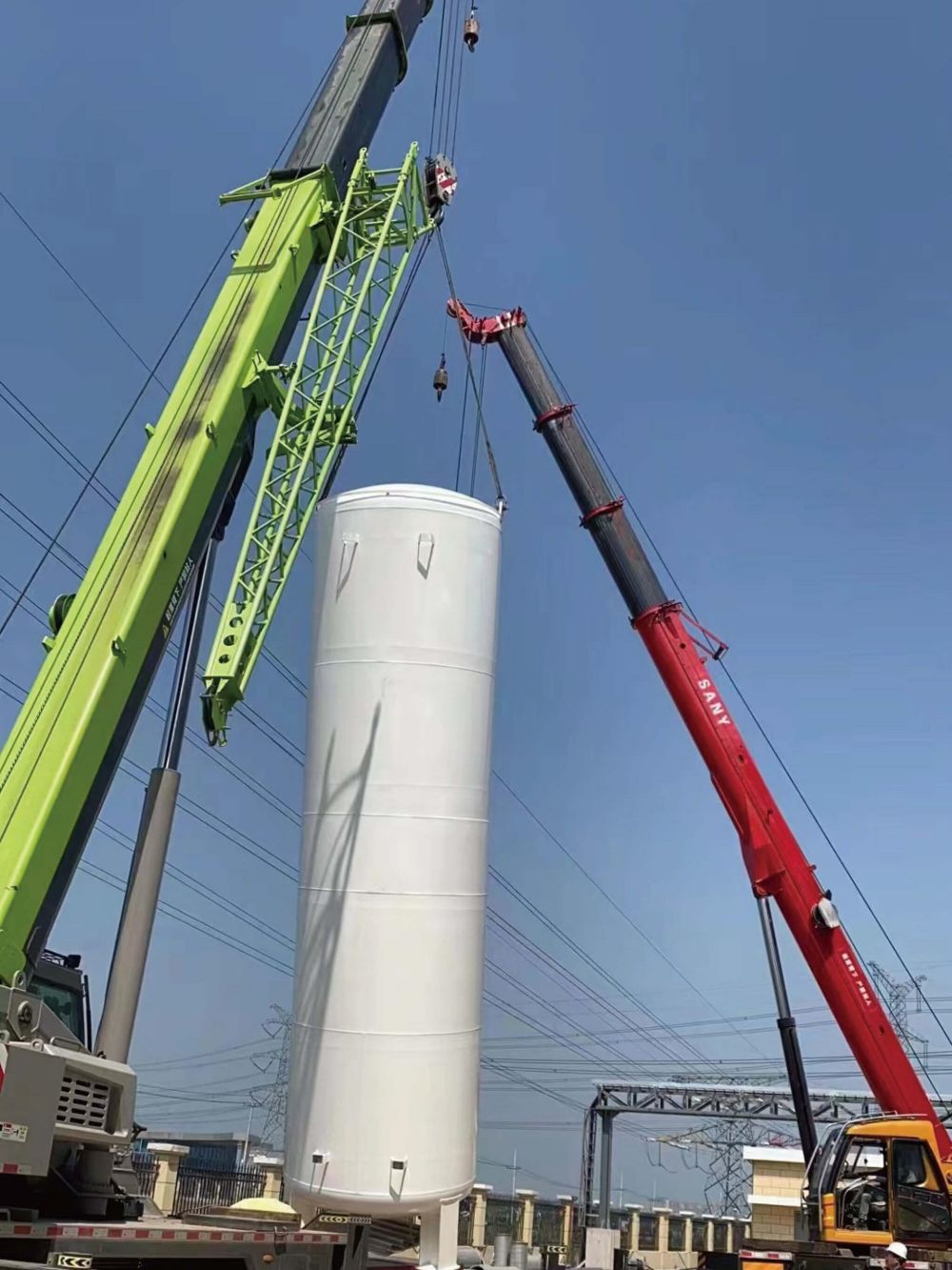
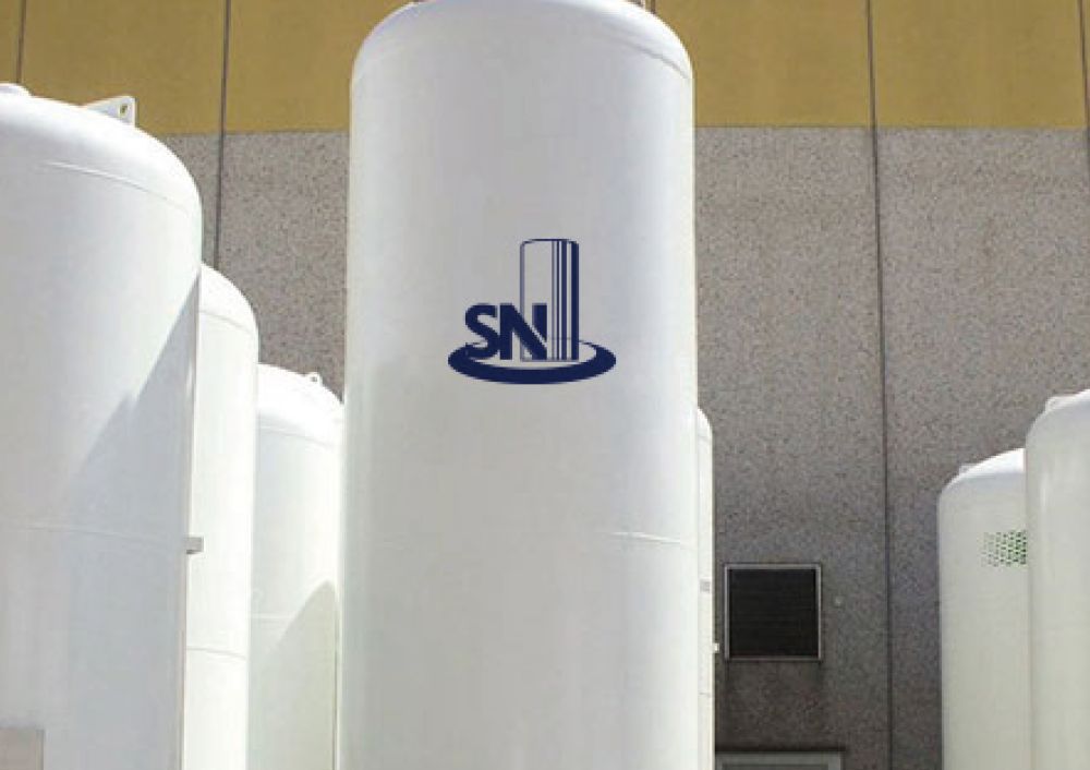
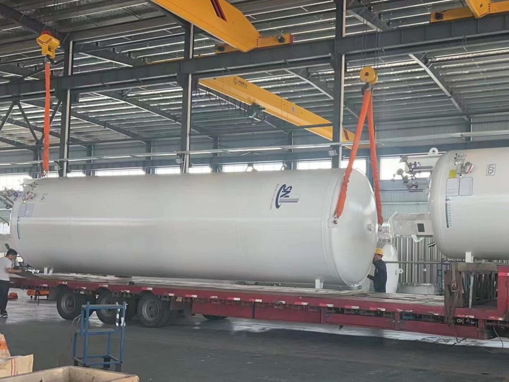
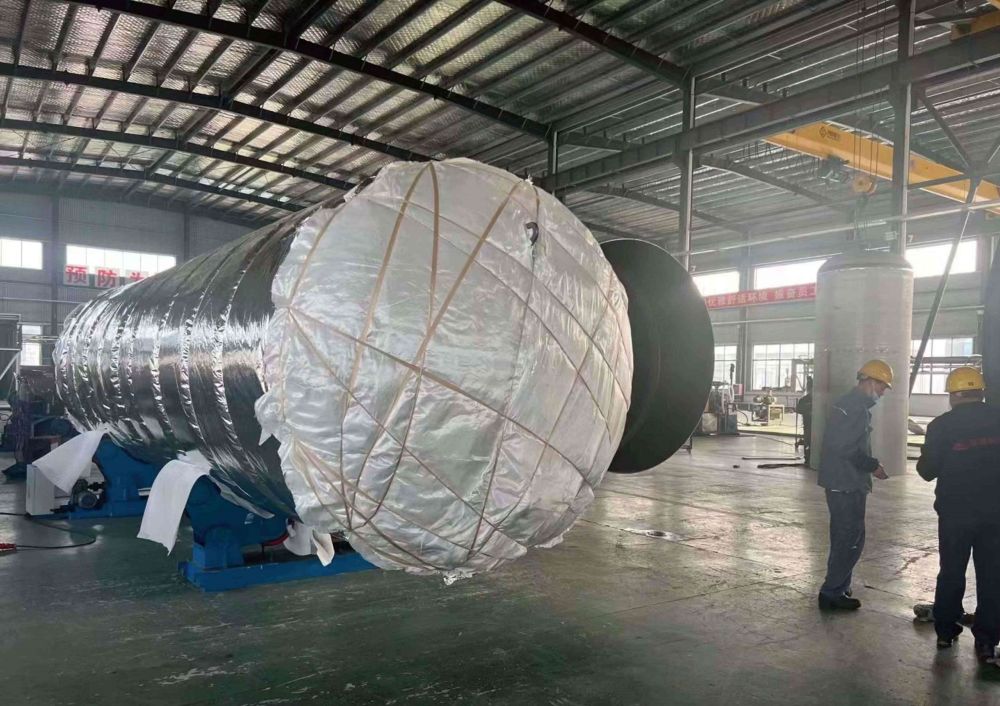
Departure Site
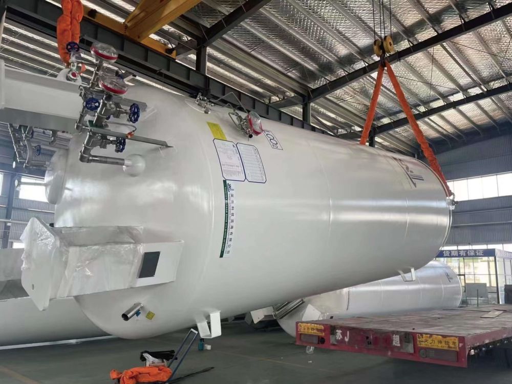
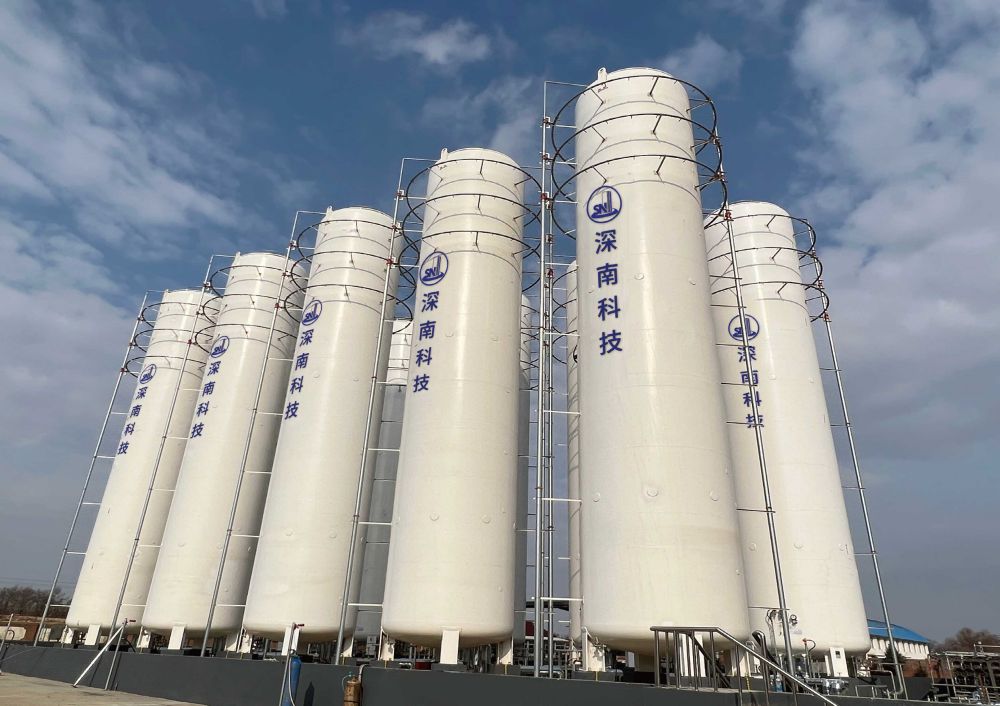
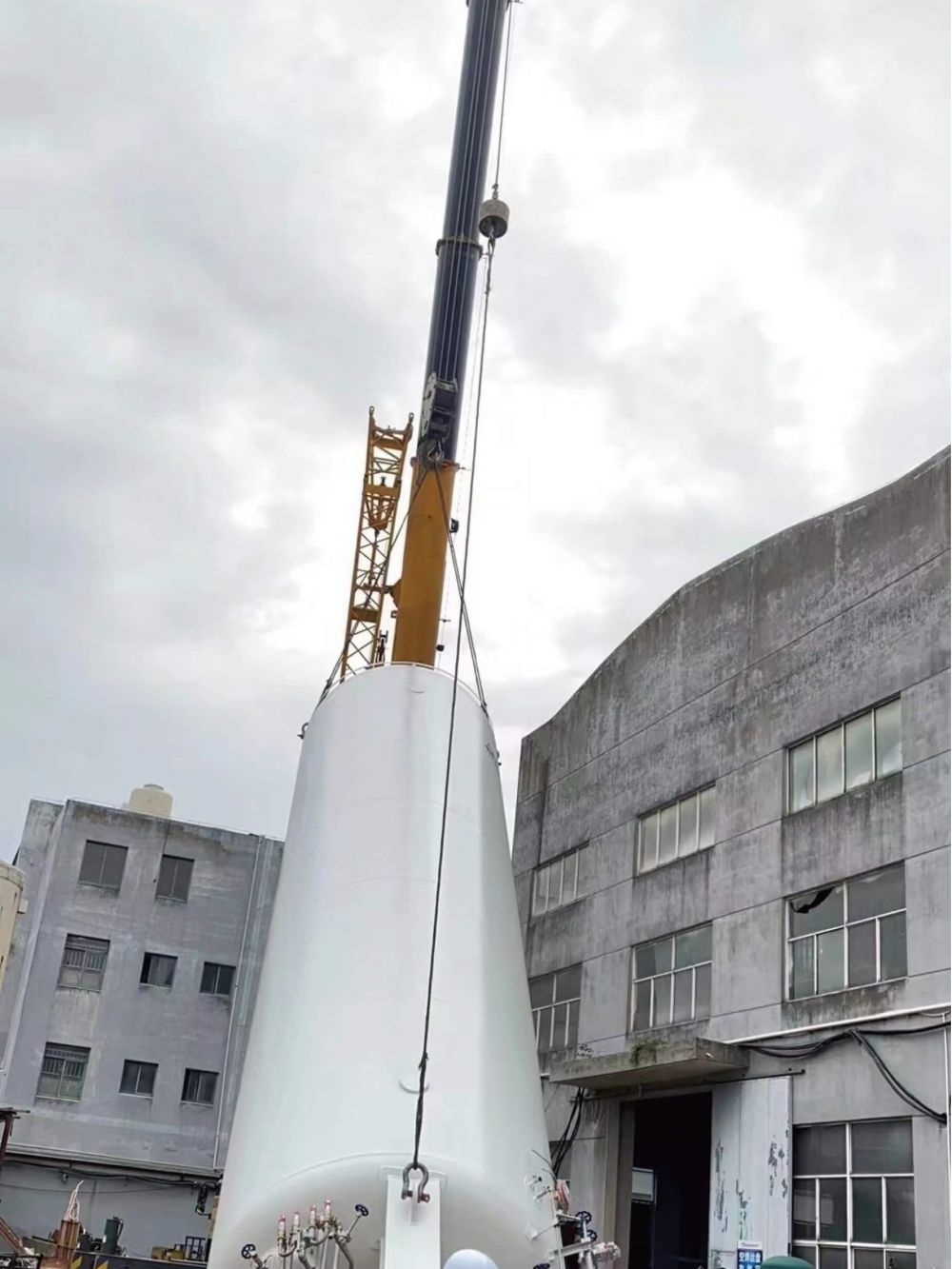
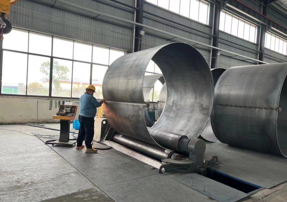
Production site
| Model | VS3/8(16)-G B | VS6/8(16)-G B | VS11/8(16)-G B | VS16/8(16)-G B | VS21/8(16)-G B | VS30/8(16)-G B | VS40/8(16)-G B | VS50/8(16)-G B | |
| working pressure bar | 8(16) | 8(16) | 8(16) | 8(16) | 8(16) | 8(16) | 8(16) | 8(16) | |
| geometric volume (㎥) | 3.16 | 5.16 | 11.14 | 15.95 | 20.76 | 30.4 | 40.17 | 49.22 | |
| Effective volume (㎥) | 3 | 5 | 10.58 | 15.15 | 19.72 | 28.88 | 38.16 | 46.76 | |
| medium | Liquid oxygen, liquid nitrogen, liquid argon | ||||||||
| Evaporation rate(%)/D(liquid nitrogen) | 0.6 | 0.435 | 0.36 | 0.35 | 0.33 | 0.29 | 0.25 | 0.23 | |
| Dimensions(mm) | Width | 2,100 | 2,100 | 2,250 | 2,250 | 2,250 | 2,800 | 3,080 | 3,080 |
| high | 2,150 | 2,150 | 2,350 | 2,350 | 2,350 | 2,820 | 3,100 | 3,100 | |
| long | 3,750 | 5,232 | 6,355 | 8,355 | 10,355 | 10,575 | 10,750 | 12,750 | |
| equipment weight(kg) | 3,760(3,825) | 4,890(3,085) | 6,980(7,490) | 9,080(9,800) | 10,450(11,370) | 10,450(11,370) | 19,130(20,820) | 22,210(24,260) | |
Note:
The data in brackets are the parameters corresponding to 17bar standard tanks
The filling rate is 95% (in the case of 1.013bar)
The above parameters are design values and are for reference only, the actual data shall be subject to measurement
The height of the siphon tank is usually about 500mm-1000mm higher than the corresponding standard tank
Special pressure, volume and flow specifications can be customized according to user requirements
Condition Diagram For Vessel:

Products categories
-
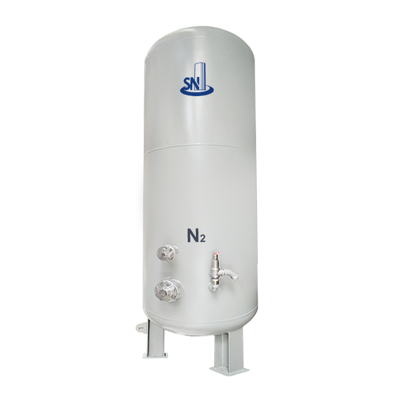
N₂ Buffer Tank: Efficient Nitrogen Storage for ...
-
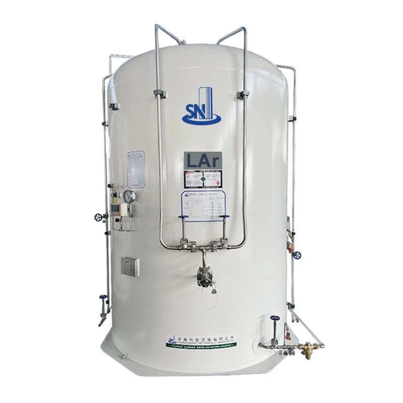
MTQLAr Storage Tank – High-Quality Cryoge...
-
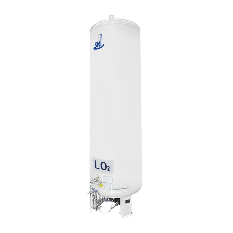
High-capacity Vertical LO₂ Storage Tank –...
-
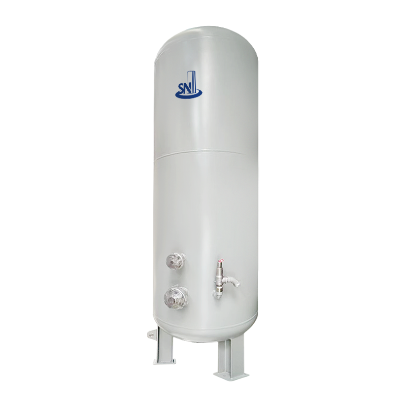
Buffer Tank – The Perfect Solution for Ef...
-
HT(Q)LNG Storage Tank – High-Quality LNG ...
-

HT-C Horizontal Cryogenic Liquid Storage Tank f...
